A Technical Study on Hard Polyurethane Foam Anti-Corrosion and Insulation Coating for Buried Steel Pipelines
A Technical Study on Hard Polyurethane Foam Anti-Corrosion and Insulation Coating for Buried Steel Pipelines
Abstract: This comprehensive study delves into the technology of Hard Polyurethane Foam (HPU) as an integrated anti-corrosion and insulation coating for buried steel pipelines. It systematically explores the material properties, the manufacturing process (primarily focusing on continuous ), key performance parameters, failure mechanisms, quality control measures, and comparative analysis with other coating systems. The research highlights the critical factors that ensure the long-term integrity and thermal efficiency of pipelines in demanding service environments, particularly for district heating and crude oil transportation. Supported by extensive data tables and detailed discussions, this report serves as a technical reference for engineers and professionals in the pipeline industry.
Keywords: Buried Steel Pipeline, Polyurethane Foam Insulation, Anti-Corrosion Coating, Cathodic Protection, Mean Life Cycle, Thermal Conductivity, Adhesion Strength, Water Absorption, Factory Applied Coating.
1. Introduction
The global demand for efficient energy transportation, particularly thermal energy for district heating and high-viscosity crude oil, has necessitated the development of highly reliable pipeline systems. Buried steel pipelines, while robust, are perpetually exposed to a trifecta of threats: corrosion from soil electrolytes, heat loss to the surrounding environment, and mechanical stress from soil movement and loading. A failure in addressing any of these concerns can lead to catastrophic economic losses, environmental damage, and safety hazards.
Traditional methods involved separate systems: a corrosion coating (e.g., fusion-bonded epoxy) for protection and an external insulation (e.g., mineral wool) for thermal conservation. However, this approach can be complex, costly, and susceptible to interface failures. The advent of Hard Polyurethane Foam (HPU) as a composite Anti-Corrosion and Insulation Coating (ACIC) system revolutionized the industry. By combining excellent thermal insulation properties with robust physical characteristics and the ability to be seamlessly integrated with a protective outer jacket, HPU systems provide a holistic solution. This study aims to provide a deep technical analysis of this critical technology.
2. Material Composition and Properties of HPU
Polyurethane foam is a polymer formed by an exothermic reaction between a polyol (resin) and an isocyanate (hardener). For pipeline applications, it is formulated to create a rigid, closed-cell foam structure.
2.1 Chemical Components:
-
Polyols: Often petroleum-based, but bio-based polyols from natural oils are emerging. Flame-retardant polyols containing phosphorus or halogen are used for enhanced fire resistance during manufacturing and handling.
-
Isocyanates: Typically Methylene Diphenyl Diisocyanate (MDI) is preferred over Toluene Diisocyanate (TDI) for pipeline foam due to its lower vapor pressure and better mechanical properties.
-
Blowing Agents: Historically, chlorofluorocarbons (CFCs) were used but were phased out due to ozone depletion. Hydrochlorofluorocarbons (HCFCs) like HCFC-141b were common but are now being replaced by zero Ozone Depletion Potential (ODP) and low Global Warming Potential (GWP) agents such as hydrofluorocarbons (HFCs, e.g., HFC-245fa, HFC-365mfc), hydrocarbons (e.g., cyclopentane, n-pentane), and water (which produces CO₂ as a blowing agent). The choice significantly impacts thermal conductivity and environmental compliance.
-
Catalysts: Amine and organometallic catalysts control the reaction speed and balance between the gelling (polymer formation) and blowing (gas formation) reactions.
-
Surfactants: Silicone-based surfactants are crucial for stabilizing the cell structure, ensuring uniform, fine, and closed cells, which is vital for low water absorption and consistent thermal performance.
-
Flame Retardants, Fillers, and Plasticizers are added to meet specific requirements like fire resistance or flexibility.
2.2 Key Physical and Mechanical Properties:
The properties of the final foam are critical for performance. The following table outlines the standard specification requirements for pipeline-grade HPU foam.
Table 1: Key Property Specifications of Pipeline-Grade Hard Polyurethane Foam
| Property | Standard Test Method | Unit | Typical Specification Range | Importance |
|---|---|---|---|---|
| Core Density | ASTM D1622 / ISO 845 | kg/m³ | 60 – 80 | Affects mechanical strength, k-factor, and cost. Higher density generally improves strength. |
| Thermal Conductivity (k-factor) | ASTM C518 / ISO 8301 | W/(m·K) | 0.020 – 0.024 (at 50°C) | Primary indicator of insulation performance. Lower values indicate better insulation. |
| Compressive Strength | ASTM D1621 / ISO 844 | kPa | ≥ 200 | Resistance to soil loading and resistance to damage during handling and backfilling. |
| Closed-Cell Content | ASTM D6226 | % | ≥ 90 | Critical for low water absorption. Higher percentage prevents moisture ingress. |
| Water Absorption | ASTM D2842 / ISO 2896 | vol% | < 5 (7-day immersion) | Determines long-term performance. Moisture ingress drastically reduces insulation value and promotes corrosion. |
| Dimension Stability | ASTM D2126 | % vol. change | < 5 (at 100°C & 100% RH for 24h) | Resistance to shrinkage or expansion under temperature and humidity cycles. |
| Adhesion Strength | ASTM D1623 / ISO 4624 | kPa | > 200 (to steel and to HDPE jacket) | Prevents disbondment, which can create water channels and shield cathodic protection. |
3. System Configuration and Manufacturing Process
The HPU coating is never applied alone. It is part of a multi-layer “pipe-in-pipe” system applied in a continuous, factory-controlled process.
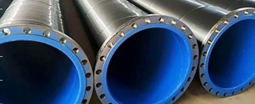
3.1 Standard System Layers (From Steel Outwards):
-
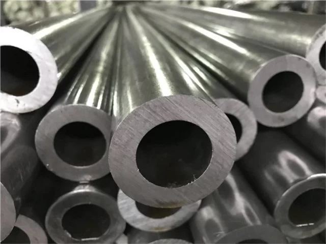
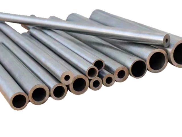
Steel Pipe: Cleaned and heated to precise temperature.
-
Fusion-Bonded Epoxy (FBE) or Anti-Corrosion Layer: This is the primary corrosion protection. It is a thin (typically 250-500 μm) epoxy coating applied electrostatically and fused to the steel. It provides excellent adhesion and cathodic disbondment resistance.
-
HPU Insulation Layer: The main foam layer, typically 25-50 mm thick, applied directly over the FBE.
-
High-Density Polyethylene (HDPE) Outer Jacket: This is the mechanical and environmental shield. It protects the soft foam from physical damage, soil stresses, and groundwater. It is also waterproof and resistant to chemicals found in soil.
Variation: In some systems, a polyethylene jacket is extruded directly onto the foam. In others, a pre-formed HDPE sleeve is pulled over the freshly foamed pipe.
3.2 The Continuous喷涂成型 Process:
This is the most common and efficient manufacturing method.
-
Surface Preparation: The steel pipe is cycled through a cleaning and heating station. It is first cleaned to a near-white metal finish (Sa 2.5) using abrasive blasting to ensure perfect adhesion for the FBE.
-
FBE Application: The heated pipe (typically 180-220°C) moves into a station where FBE powder is sprayed onto it. The heat melts and cures the powder, forming a continuous film.
-
Cooling and Inspection: The FBE-coated pipe is cooled and inspected for holidays (defects) using a high-voltage holiday detector.
-
Polyurethane Application Station: The pipe enters a long, enclosed chamber. A precision dispensing machine traverses along the rotating pipe.
-
The two liquid components (polyol and isocyanate) are held in temperature-controlled tanks.
-
They are pumped at high pressure to a mixing head where they are intensely mixed.
-
The mixture is poured onto the rotating pipe surface. It begins to react, expanding and curing to form the foam layer.
-
-
HDPE Jacket Application: Simultaneously or immediately after, the molten HDPE is extruded through a cross-head die, forming a continuous tube around the expanding foam, creating a tight mechanical bond.
-
Curing and Cooling: The coated pipe moves through a cooling tunnel where the foam’s exothermic reaction completes and the entire system solidifies.
-
End-Cutting and Final Inspection: The ends are trimmed clean to expose the steel for welding on-site. The final product is inspected for thickness, density, and integrity (e.g., ultrasonic testing for foam cohesion).
4. Critical Performance Parameters and Failure Modes
Understanding the parameters that govern performance is key to preventing failures.
4.1 Thermal Performance and Aging:
The initial k-factor is excellent, but long-term performance depends on the diffusion of gases inside the closed cells. Over time, air (mostly nitrogen and oxygen) diffuses into the cells, while the blowing gas (e.g., cyclopentane) diffuses out. This process, called thermal aging, increases the k-factor until it stabilizes. The stabilized k-factor is the design value. Using a low-conductivity gas like cyclopentane results in a lower initial k-factor but a larger aging effect. Systems with CO₂ as a blowing agent age faster but can be designed with lower density.
4.2 Adhesion and Cathodic Disbondment:
The adhesion between FBE/steel and foam/HDPE is paramount. Poor adhesion can create annular spaces. If water enters through a breach in the HDPE, it can flow through this space, compromising insulation and potentially shielding the pipe from Cathodic Protection (CP). CP is an imperative backup system for buried pipelines; if shielded, corrosion can proceed undetected. The FBE must have excellent Cathodic Disbondment (CD) resistance (e.g., < 15 mm radius after 28 days at 65°C per ASTM G8/G42).
4.3 Water Ingress:
This is the single greatest threat. Water has a thermal conductivity approximately 25 times that of HPU. Even a small volume of water absorption dramatically reduces the insulation efficiency. Furthermore, if the water reaches the steel surface, it can initiate corrosion, especially if CP is shielded. The HDPE jacket’s integrity is the first line of defense.
4.4 Mechanical Damage and Soil Stress:
The system must withstand handling, installation, and decades of soil pressure, including point loads from rocks. The composite strength of the foam and HDPE jacket distributes these loads. The foam’s compressive strength prevents crushing, which would reduce thickness and insulation value.
Table 2: Common Failure Modes and Their Mitigation Strategies
| Failure Mode | Root Cause | Consequences | Mitigation Strategies |
|---|---|---|---|
| Thermal Performance Degradation | 1. Moisture ingress. 2. Thermal aging of foam. 3. Physical damage crushing foam. |
Increased heat loss, higher energy costs, potential overheating of pipe contents. | Use of high-quality, high-closed-cell foam. Robust HDPE jacket. Proper installation to avoid damage. Designing with aged k-factor. |
| Corrosion under Insulation (CUI) | 1. Breach in HDPE jacket. 2. Poor adhesion creating water channels. 3. Shielding of Cathodic Protection. |
Loss of pipe integrity, leaks, catastrophic failure. | Excellent FBE CD resistance. 100% holiday detection of HDPE. Ensuring CP system is designed for and can penetrate the coating system. |
| Foam Shrinkage/Cracking | 1. Poor foam formulation. 2. Excessive operating temperatures. 3. Poor dimensional stability. |
Creates annular space for water migration, reduces insulation. | Strict quality control of raw materials and process parameters. Ensuring operating temp is within foam’s rating. |
| HDPE Jacket Damage | 1. Improper handling. 2. Sharp rocks during backfilling. 3. Soil stress cracking. |
Direct entry point for water and soil. | Use of thicker HDPE jackets for deeper burial. Sand padding during installation. Proper bedding and backfill material. |
5. Quality Control and Testing Regime
A rigorous QC protocol is essential from raw materials to finished pipe.
Table 3: Quality Control Tests for HPU Coated Pipes
| Stage | Test | Standard | Frequency / Purpose |
|---|---|---|---|
| Raw Materials | Polyol/Isocyanate reactivity, viscosity, etc. | In-house specs | Per batch shipment |
| HDPE resin melt index, density | ASTM D1238, D792 | Per batch shipment | |
| FBE powder gel time, particle size | ASTM D3794 | Per batch shipment | |
| In-Process | Steel surface profile & cleanliness | ISO 8501, SSPC-VIS 3 | Every pipe |
| Steel pre-heat temperature | Pyrometer | Continuous | |
| FBE thickness | DFT Gauge | Continuous | |
| Foam density & thickness | Gamma density gauge, ultrasonic | Continuous | |
| HDPE thickness | Ultrasonic gauge | Continuous | |
| Finished Pipe | Holiday detection on FBE & HDPE | ASTM G62, NACE RP0274 | Every pipe |
| Adhesion strength (foam to steel, foam to HDPE) | ASTM D1623 | Destructive test on first, last, and sample pipes per shift | |
| Foam core sampling for density, k-factor, closed-cell | ASTM D1622, C518, D6226 | Destructive test on sample pipes per shift/production run | |
| Overall electrical continuity for CP | Every pipe |
6. Comparative Analysis with Alternative Systems
While HPU is dominant, other systems are used for specific applications.
Table 4: Comparison of Buried Pipeline Insulation Systems
| Coating System | Typical Structure | Advantages | Disadvantages | Typical Applications |
|---|---|---|---|---|
| HPU + HDPE Jacket | Steel -> FBE -> HPU -> HDPE | Excellent insulation, factory-applied quality, integrated system, good mechanical protection. | Risk of widespread failure if CP is shielded, repair can be complex, limited upper temperature (~120-140°C). | District Heating, Chilled Water, Crude Oil |
| Mineral Wool + PE Jacket | Steel -> FBE -> MW -> PE | Very high temperature resistance (>200°C), non-combustible, CP not shielded. | Thicker, heavier, less efficient insulation (higher k-factor), can absorb water if jacket fails. | Steam lines, Very high-temp oil lines |
| Syntactic Concrete | Steel -> FBE -> Concrete | Negative buoyancy for submarine pipes, excellent mechanical protection. | Very heavy, very poor insulation, requires additional insulation layer if needed. | Submarine Pipeline Ballast Weight |
| Pipe-in-Pipe (PIP) | Carrier Pipe -> Insulation -> Outer Casing | Can use multiple insulants (e.g., aerogel), highest thermal performance, complete mechanical protection. | Extremely high cost, complex fabrication and installation, very heavy. | Deepwater Flowlines, Long-distance subsea tie-backs |
7. Installation, Field Jointing, and Repair
The best factory coating can be compromised by poor field practices.
7.1 Installation: Pipes must be handled with care using wide-belt slings to avoid damaging the HDPE. The trench must be prepared with a bed of sand or fine soil without sharp rocks. Proper padding and backfilling are crucial.
7.2 Field Jointing: This is the most critical and challenging aspect. After welding two pipe sections, the exposed steel weld and the cut-back ends of the coating system must be insulated and protected to the same standard as the factory coating.
-
The weld is cleaned and inspected.
-
A FBE sleeve or liquid epoxy is applied to the weld area for corrosion protection.
-
A “field joint foam kit” is used. This typically involves placing a pre-formed HDPE sleeve over the joint and injecting two-component polyurethane foam into the cavity. The foam expands to fill the space.
-
The ends of the sleeve are heat-fused to the mainline HDPE jacket to ensure continuity.
-
Every field joint is rigorously inspected.
7.3 Repair: Damage to the HDPE jacket identified before burial can be repaired using heat-shrink sleeves or specialist patches sealed with extrusion welding. The integrity of the fusion is critical.
8. Environmental and Economic Impact
The shift to low-GWP blowing agents is a significant industry trend driven by environmental regulations like the Kigali Amendment to the Montreal Protocol. Hydrocarbon-based systems (cyclopentane) are now standard, despite being flammable and requiring upgraded factory safety measures.
Economically, the HPU system offers a lower total cost of ownership for most heating applications. The higher initial material and factory application cost is offset over the pipeline’s lifespan (often 30+ years) by significantly reduced energy losses compared to less efficient systems.
9. Conclusion and Future Trends
Hard Polyurethane Foam insulation, integrated with a robust anti-corrosion layer and an HDPE outer jacket, remains the preeminent technology for thermally efficient buried steel pipelines. Its success hinges on a deep understanding of the material science, a rigorously controlled manufacturing process, and meticulous attention to installation and field jointing details.
Future research and development are focused on:
-
Next-Generation Blowing Agents: Developing and commercializing blowing agents with zero ODP and ultra-low GWP that do not compromise the k-factor or processability.
-
Bio-based Polyols: Increasing the renewable content of the foam to improve sustainability without sacrificing performance.
-
Enhanced Monitoring: Integrating optical fiber sensors within the foam layer or between the foam and jacket for real-time monitoring of temperature profiles along the entire pipeline length, allowing for leak detection and condition assessment.
-
High-Temperature Foams: Developing formulations that can withstand temperatures above 150°C to expand the application range into higher-temperature district heating and industrial processes.
-
Advanced Repair Technologies: Developing faster, more reliable, and verifiable field joint and repair techniques to further reduce lifecycle risks.
The continuous improvement of this mature technology ensures it will remain a cornerstone of efficient and safe energy infrastructure for decades to come.